DIAPHRAGM WALL, BRIdGES & ETC
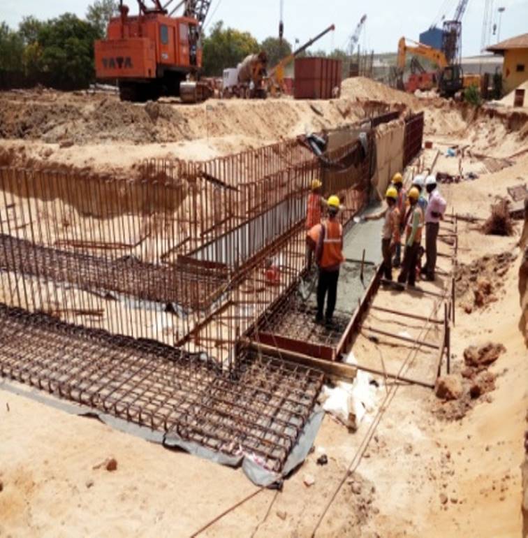
Setting out & Construction of Guide Wall
- Survey and setting out operation shall be carried out according with approved drawings.
- Guide wall trench excavation will be excavated by JCB/ Poclain for guide wall of 1.2 mtrs depth from the existing ground level.
- Guide wall will be constructed by inverted "L" shaped RCC wall and forming a support to the earth and prevents it from collapse when the boring of Diaphragm wall .Guide wall will be constructed prior to the excavation of the Diaphragm wall and will be made with M20 grade of concrete as per approved design mix.
The purpose of Guide Wall
- To provide a permanent alignment for the Grabbing of diaphragm wall.
- To provides edge protection to the diaphragm wall and to prevent the collapse of top soil during the excavation /grabbing.
- To act as a platform to hang reinforcement cage and maintain the level.

Excavation of Diaphragm wall by using Grab fitted to hydraulic rig
- The diaphragm wall will be located between the guide wall .The guide wall will be marked with the panel reference number and centre line of stop end position. The guide wall will be strutted and backfilled prior to excavation to prevent movement or settlement.
- Prior to commencing actual excavation /grabbing the grab fitted with rig will be set up vertically either on one side of the guide wall axis.
- The trenching will be carried out by the grab attached to the hydraulic rig .Excavation by grabbing will be done in presence of the Bentonite mud solution. The density of Bentonite mud solution for circulation will be kept more than the normal density to ensure the stability of the trench.
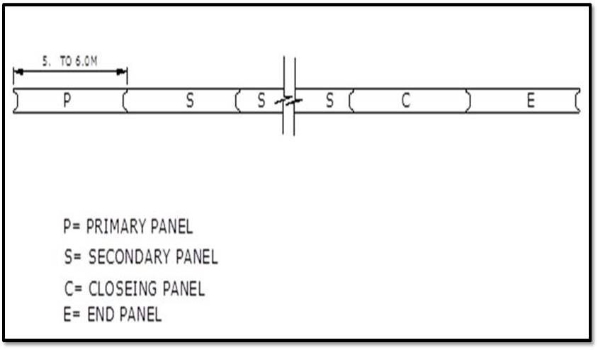
Construction of Diaphragm wall panel sequence
- Primary Panel
- Secondary Panel
- Closing Panel
- The Primary panel is the starting panel, which is cast with two nos of stop end in place. These panels are logically placed to suit construction schedule. The panel proceeds in both directions from the primary panel using secondary panels, which are cast with a single stop end in place. The closing panel is the final panel, which is cast after the removal of the both stop end.
- The panel length is defined as the distance between the centre line of the two stop end (including the water stopper) .The orientation of the stop end can therefore by changed without effect to the reinforcement cage position on site.
- The panel installation sequence and therefore panel types are in most cases interchangeable and thus the sequences of installation can be modified to adapt to the conditions experienced on site provided that the length of the panels being considered is the same.
Bentonite Mud
- Bentonite should be tested as per standard operating procedure .The diaphragm wall excavation / grabbing will be done by bentonite mud circulation to prevent collapsing /caving in soil inside panel. Bentonite shall be stored /prepared in a designated area as mentioned above.
- To assure that bentonite slurry /mud is in according with standard operating procedure using mixing tank motor pump for bentonite mixing mud circulation .The quality of bentonite slurry /mud used for the excavation /grabbing will be verified during preparation and excavation ,prior to concreting (before steel cage lowering).
Checking parameter
- Density
- PH Value
The site shall be equipped with the following instruments
- Fluid sampler
- Marsh funnel
- Graduated cylinders or cup
- PH papers
- Other necessary equipments and apparatus - from Concrete supplier end to take care slump cone for slump test and cubes for compression strength.
- Fixing of water stopper in stop end grooves & lowering of the stop end.
- After completion of excavation or trench, the stop end along with the water stoppers will be installed.
- After completion of grabbing up to required depth the trench will be cleaned. The stop end will be cleaned greased and the water stopper will be fixed in the stop end groove and to be ensured that while lifting the stop end the water stoppers do not slip from the groove .Before lowering the cage the stop end attached with the water stoppers and lowered in the trench which mark the boundary of panel so that fresh concrete does not come in direct contact with the soil in the next panel.
- As stated above primary panel shall have two nos of stop end, secondary panel shall have one stop end closing panel shall have no stop end.
- The stop end will be lowered straight and shall be kept vertical with the help of concrete block. After fixing the stop end, the panel dimensions will be checked and ensured that it should be within tolerance limits verticality will be checked and monitored with the help of plumb-bob and sprit level keeping parallel and perpendicularly to the stop end .
Note: - Approved water stopper & with proper size information shall be supplied free of cost by client. With this information we will fabricate the stop end to accommodate the water stopper.
Reinforcement Cage fabrication & Lowering
- The specified reinforcement cage will be fabricated on the ground and welded depending upon the site condition and equipments availability the cage may be fabricated and lowered in two or four parts.
- The reinforcement should be cut and bent at the steel yard or at site as per the approved stop end drawing and the cage will be prepared/ fabricated at the site over a level ground .Care will be taken to fabricate the cage in true line and level with cover blocks fixed with proper supports and will be shifted to the panel location with the help of crane. Tack weld will be done to cage to avoid any deformation during lifting process.
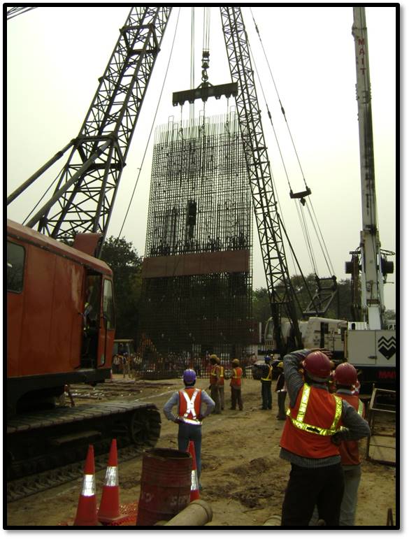
- Cage Lifting & placing
- Before starting the erection of cage the following precautions will be taken care
- Barricading will be provided for guide wall
- Proper lifting and erection will be done carefully lowered vertically downward and supervision for avoiding the edge breaking to guide wall.
- Lifting & placing of cage will be done with the help of 02 nos of crane and the cage lifter assembly. The cage lifter will be fixed directly to the lifting hooks of the cage with D shackles and slings of the 50 MT Lifting capacity cranes. The bottom end of the cage shall be fixed to the second crane (minimum 50 MT capacity service crane) with two slings will be ensured.
- The lifting beam will be designed according to the calculation provided by design team will be ensured for fabrications.
- The cage will be lifted slowly with 50MT crane operating both the sling and bottom shall be lifted by the supporting second crane which wills move at a synchronized speed with the movement of the cage under skilled supervision. When the cage is fully lifted the load in service crane shall be free so that the entire load of the crane will come on the 50 MT crane.
- After completion of lifting process the cage will be lowered slowly into the panel and positioned with verifying the line verticality with plumb- bob
The cage will be properly tagged as below
- Panel no.
- Status of inspection
- Approved for use
Tolerance as below
- Longitudinal tolerance of cage head at the top of the guide wall and measured along the trench +/- 75mm
- Vertical tolerance of cage head in relation to the top of the guide wall +/- 5mm
- Lateral tolerance of reinforcement position In the direction across the width of wall shall be +/-50mm
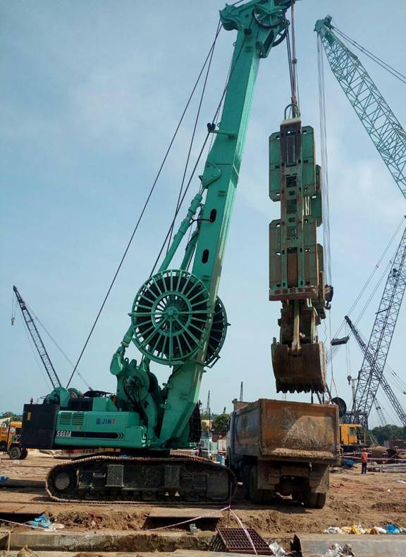
Hydraulic Ram for Trenching